


DOE Laser Modules: A Practical Guide to Precision Beam Shaping

If you have ever projected a laser line onto a surface and noticed that the centre glows noticeably brighter than the edges — fading into a soft, uncertain blur the further out you go — you have just had a firsthand encounter with the Gaussian problem. It is not a defect. It is physics. And for many precision applications, it is a real obstacle.
Conventional laser modules use refractive optics — glass or plastic lenses ground into smooth curves — to redirect and focus light. This works perfectly well for simple pointer applications or rough alignment tasks. But when your machine vision system needs to detect an edge to within a fraction of a millimetre, or when your industrial alignment jig needs to project a reference line that stays sharp and consistent across a two-metre working range, the soft shoulders of a Gaussian beam become a genuine engineering problem.
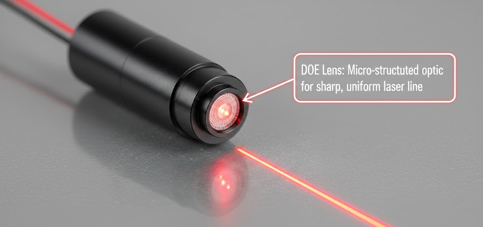
This is where Diffractive Optical Elements, or DOEs, come in. Rather than bending light through curved surfaces, a DOE uses microscopic patterns etched directly into an optical substrate — patterns that interact with the wavefront of the incoming laser beam through diffraction, redistributing the energy into precisely defined shapes. The result is a fundamentally different kind of projection: sharper edges, more controlled intensity profiles, and patterns that hold their geometry at extended distances.
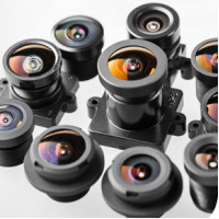
IADIY's DOE Pattern Laser Module series covers four distinct patterns — Line, Cross-hair, Circle with Centre Dot, and Circular Spot (Diffuser) — each engineered for specific professional applications. This guide explains the physics behind DOE optics, describes the real-world behaviour of each pattern, and helps you choose the right module for your project.
To appreciate what DOE technology solves, it helps to understand exactly what a Gaussian beam profile looks like in practice.
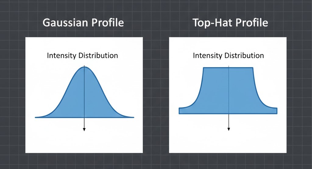
In a standard refractive laser module, the intensity of the projected beam follows a bell-curve distribution. Maximum energy concentrates at the centre, and it falls off smoothly toward the edges. On a beam profile plot, this looks elegant. In a real application, it creates three concrete problems.
Edge definition loss is the most immediate issue. The gradual roll-off from bright centre to dim edge produces a transition zone where the light is neither clearly "on" nor clearly "off." Vision algorithms that rely on edge detection struggle with this ambiguity. The wider the Gaussian tail, the less confident the detection, and the greater the position error.
Centre saturation compounds the problem. If you set camera exposure to correctly capture the edge region, the centre may already be overexposing and blooming. If you optimise for the centre, the edges become too dim to detect reliably. This is a particularly frustrating tradeoff in high-dynamic-range scenarios.
Distance-dependent degradation means the beam does not behave the same at 0.5 m as it does at 2 m. As projection distance increases, the edge energy disperses faster than the centre, causing the useful pattern to visually shrink even as the geometric projection grows. In scanning or triangulation setups, this inconsistency introduces systematic errors.
None of these are unsolvable with a standard module — clever image processing can compensate to a degree. But every compensation step adds latency, software complexity, and calibration overhead. The DOE approach addresses the root cause instead.
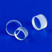
The core of a DOE (Diffractive Optical Element) is a microscopic surface relief pattern etched into an optical substrate. Unlike a conventional lens that bends light through curved surfaces, a DOE works by modulating the phase of the incoming laser wavefront across its full aperture. Each microscopic region of the etched surface introduces a precisely calculated phase shift. As these phase-shifted waves propagate forward, they interfere with each other — constructively reinforcing light in the desired output locations and destructively cancelling it everywhere else. The result is a specific, repeatable pattern — a line, a grid, a circle — reconstructed entirely from the physics of interference, requiring no moving parts or refractive curvature.
When integrating these modules, one characteristic that engineers consistently observe is a relative increase in brightness at the exact centre of the projected pattern. Several physical factors can contribute to this effect — residual Gaussian intensity from imperfect beam collimation, finite aperture diffraction artefacts, and phase quantisation errors introduced during fabrication — but the dominant cause is zero-order leakage.
In any diffractive system, a small percentage of the original laser energy passes through the optic without being diffracted into the intended pattern. This undiffracted "zero-order" light continues along the original optical axis. Because it remains concentrated at the centre rather than being spread across the full pattern, it appears as a brighter focal point superimposed on the projected image.
While some might view this as an irregularity, we treat it as a deliberate characteristic of the module's optical signature — and in practice, it turns out to be genuinely useful. Consider the cross-hair pattern: the central spot naturally falls at the intersection of the two projected lines, giving machine vision algorithms and human operators alike a single, high-contrast point to lock onto. The same principle applies wherever a precise spatial anchor matters. Rather than attempting to suppress this leakage through extreme manufacturing tolerances — which would significantly increase costs without changing the underlying physics — we recommend that integrators embrace it.
As we explore in the following sections, this central bright spot functions as a highly reliable computational anchor and a clear visual reference point across each of our four pattern types, making the patterns easier for both human eyes and machine vision algorithms to work with.
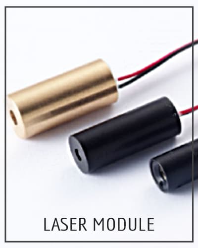
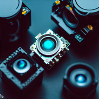
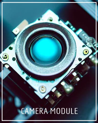
IADIY's DOE laser modules are built around a standard Φ9 mm full-metal barrel. This is not just a cosmetic choice — the construction directly affects long-term performance in deployed systems.
Metal housing provides significantly better thermal management than plastic alternatives. Laser diodes are sensitive to junction temperature, and sustained operation at elevated temperatures accelerates performance degradation and reduces lifetime. A metal barrel acts as a passive heat spreader, drawing heat away from the diode and DOE element and dissipating it into the surrounding mechanical assembly or housing. This matters especially in continuously-running industrial systems.
Mechanical robustness is equally important. The Φ9mm barrel withstands vibration, minor impact, and the physical stress of being mounted and remounted during development and integration. Thread-on or press-fit mounting in standard fixtures is straightforward, and the 9mm diameter is a widely recognised standard dimension in the laser module industry, meaning compatible mounts, holders, and housings are readily available from multiple suppliers.
From an environmental standpoint, metal provides better protection against humidity, condensation, and airborne contaminants than plastic — all of which are relevant in factory, outdoor, or laboratory settings.
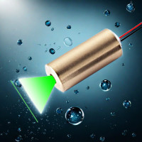
Traditional refractive line lasers typically project at fan angles of 15° or more. This produces a usefully long line at close range, but the energy disperses rapidly with distance. At longer working ranges, the line becomes dim and the edges degrade.
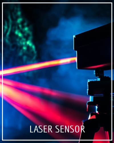
IADIY's DOE Line modules can achieve fan angles as narrow as 4°. At this angle, the energy stays concentrated in a narrow strip — the line remains bright and well-defined across significantly greater distances. This matters for applications like 3D structured-light scanning, surface height measurement, and laser triangulation sensors, where the working distance may be 1–3 metres and consistent line quality throughout that range is essential.
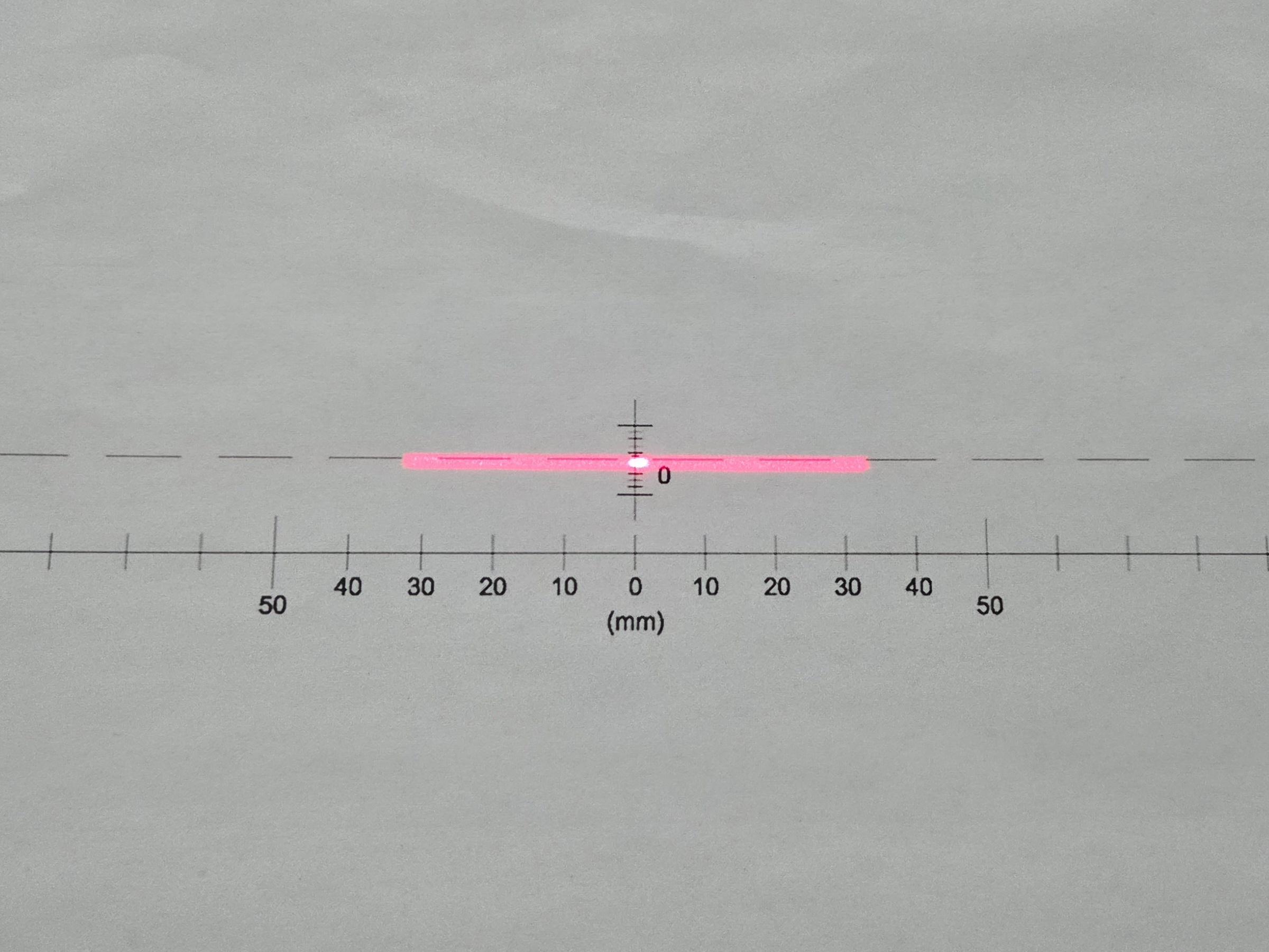
Visually, the DOE Line produces a distinct appearance that experienced users often describe as crisper or more "rectangular" than a conventional line — the projected strip has a more defined width and sharper lateral edges. In applications where the laser line is visible to an end user or operator, this contributes to a more professional and confident appearance.
Application examples include precision woodworking for grain and cut alignment, natural stone fabrication, structural steel positioning, and laser triangulation sensors for robotic guidance.
A cross-hair pattern projects two intersecting lines at right angles, creating an X-Y reference frame at the point of projection. IADIY's DOE Cross-hair module is designed to ensure that the intersection — the most functionally important point in the pattern — is clearly visible and unambiguous.
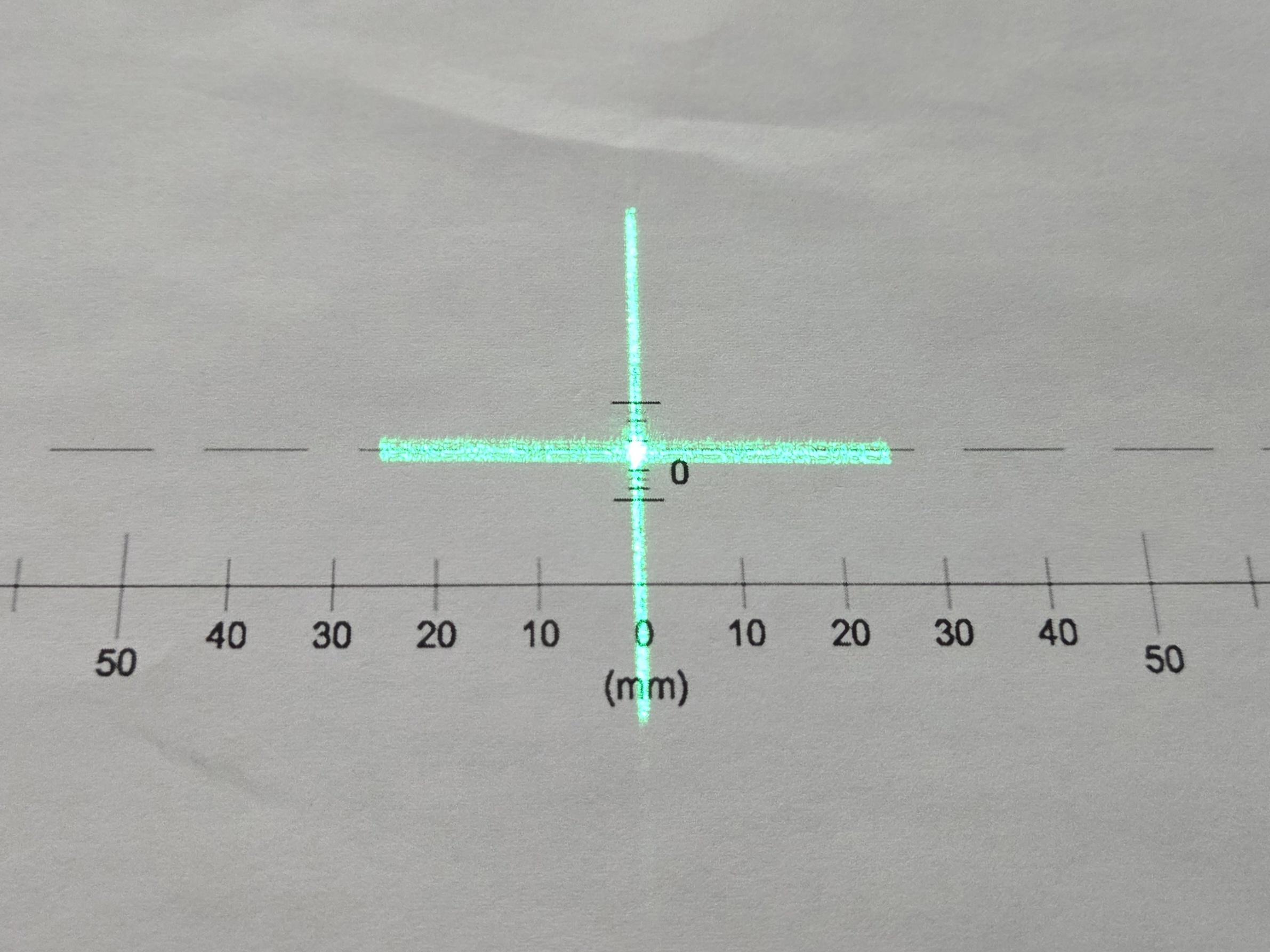
The natural tendency toward central intensity enhancement actually serves this pattern particularly well. The intersection of the two lines already accumulates more energy by geometry (it is the only point covered by both lines), and the DOE intensity characteristic reinforces this. The result is a cross-hair with a bright, easily identifiable centre that acts as a precise spatial reference for both human operators and automated systems.
This makes the DOE Cross-hair well-suited to PCB drilling registration, industrial X-Y stage positioning, patient positioning in medical radiation therapy systems, and optical alignment tasks in instrument manufacturing.
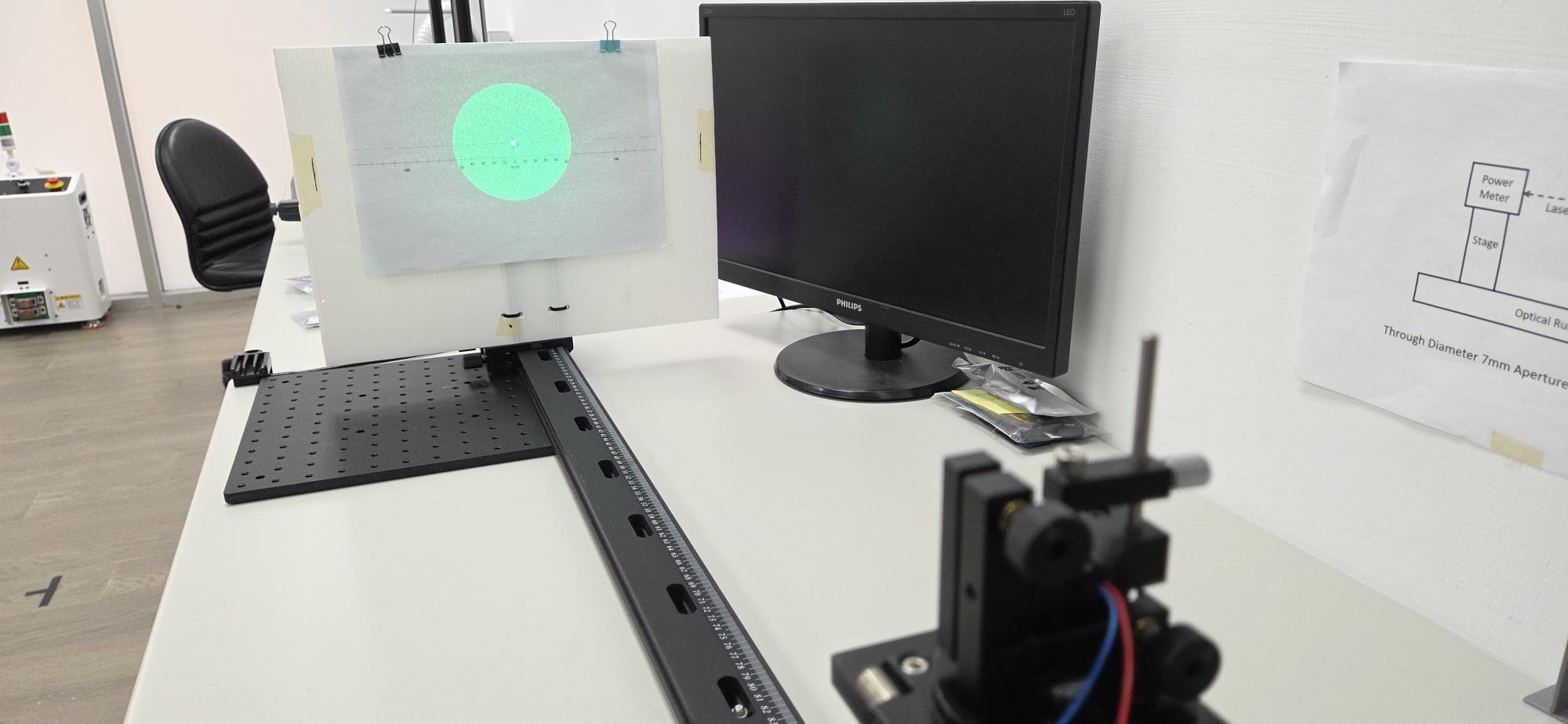
The Circle with Centre Dot pattern projects a circular boundary ring together with a co-axial point at the geometric centre. This dual-feature design solves a specific problem that arises when working with symmetric objects: a simple circle tells you the boundary, but not the centre. A simple dot tells you the centre, but not the boundary. Having both simultaneously removes an entire category of positioning ambiguity.
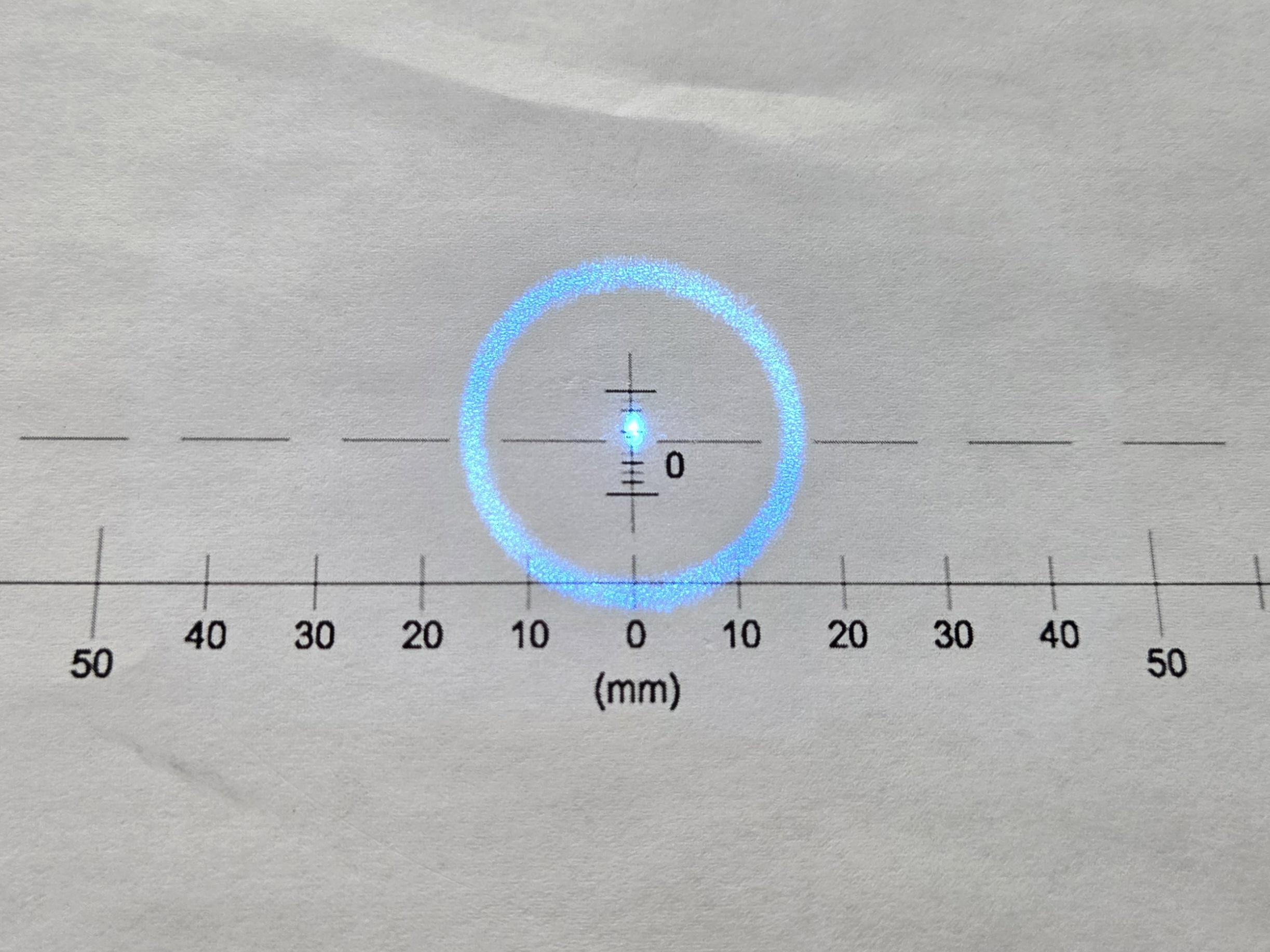
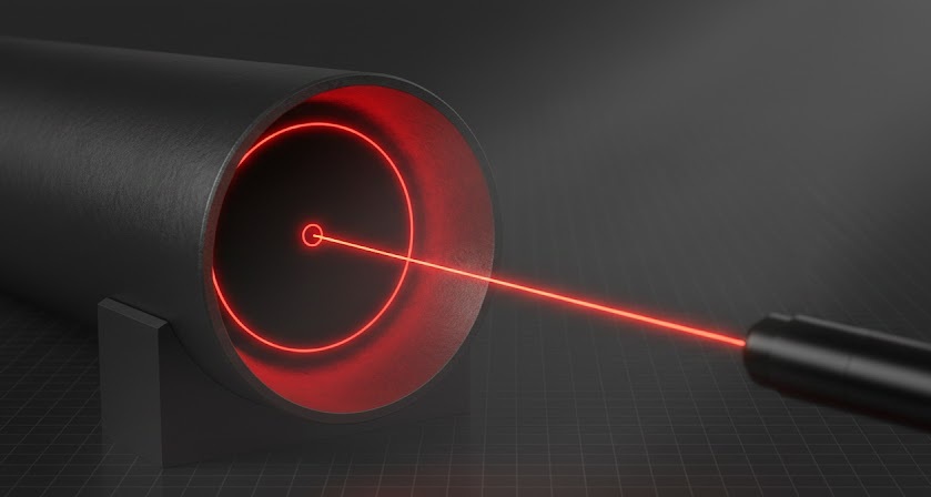
The centre dot in this pattern is a designed feature of the DOE, not a side effect. Combined with the natural central intensity enhancement, it is rendered with high visibility and positional certainty. For automated inspection systems examining circular parts — pipe ends, O-rings, lens elements, connector mating faces — the ability to simultaneously verify both diameter and concentricity in a single camera frame is a meaningful simplification.
Application examples include pipe and tube end inspection, circular component centring in automated assembly lines, precision lens mounting and alignment, and bearing race inspection.
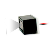
The Circular Spot module, sometimes called a diffuser pattern, transforms a collimated point source into a uniform disk of illumination. This is the pattern where the top-hat goal is most critical — and where departing from it matters most.
A standard laser spot has extreme intensity at the centre and is entirely unsuitable for area illumination, fluorescence excitation, or any application where uniform power density is required. The DOE Circular Spot redistributes this into a flat-top disk with sharp outer boundaries.
Because this pattern is specifically designed for homogeneous illumination, it is the most demanding in terms of fabrication precision. Applications that genuinely require flat power density — such as fluorescence excitation in material science, photolithography alignment marks, or calibration reference illumination — should evaluate this module carefully and confirm that the power uniformity specification meets their requirements.
Other application examples include compact task lighting for surface inspection stations, laser art installations requiring clean circular light elements, and laboratory sample illumination.
IADIY's DOE modules are available in several wavelengths, and the choice has practical consequences beyond personal preference.
- 635 nm (high-visibility red) is perceived as approximately three to four times brighter to the human eye than 650 nm at the same optical power, due to the shape of the photopic sensitivity curve. This makes 635 nm the better choice for applications in high ambient light conditions — outdoor construction, workshop environments, or anywhere the laser competes with strong overhead lighting.
- 650 nm (standard red) offers excellent compatibility with silicon-based camera sensors, which have high quantum efficiency in the red range. It is the most cost-effective option and entirely suitable for controlled-light environments where ambient illumination is managed.
- 520 nm (direct green) sits near the peak of the human visual sensitivity curve. It is the most visible wavelength per milliwatt to the human eye under daylight conditions, making it the top choice for daylight-visible applications and for machine vision setups where the camera is monochrome and sensitivity across the visible range matters.
- 405 nm / 450 nm (violet and blue) take advantage of shorter-wavelength diffraction to achieve the finest possible feature sizes — narrower line widths and smaller spot diameters. These wavelengths are appropriate for high-resolution measurement, semiconductor inspection, and applications where minimum achievable feature size drives performance.
All IADIY DOE laser modules comply with IEC 60825-1, the international standard for laser product safety. Modules are classified and tested according to their output power and application requirements.
One important note for integrators: a DOE module that passes through the DOE optic will typically have a different hazard classification than the raw laser diode output alone, because the DOE redistributes energy. Always assess the safety classification of the complete assembled module — not the diode in isolation — and ensure your product certification is based on the full module output.
IADIY provides optical specifications and test data to support product certification processes. Consult a qualified laser safety officer when integrating any laser module into an end-user product, particularly those intended for medical, industrial, or consumer markets.
- Working distance and pattern size are directly related in DOE projection systems. The projected pattern size scales linearly with distance. Specify your working distance range early, and confirm that the pattern dimensions at both minimum and maximum distance are compatible with your sensor field of view and spatial resolution requirements.
- Minimum pattern formation distance is a real constraint for DOE optics. Very close to the module exit aperture, the diffracted pattern has not fully formed. Each module has a minimum working distance below which the pattern will appear incomplete or distorted. This is typically in the range of tens of millimetres and should be confirmed for your specific application.
- Drive electronics for DOE modules follow standard constant-current laser diode requirements. The DOE element itself is passive — it adds no electrical requirements. Stable current drive is important for consistent power output; optical power fluctuation directly affects intensity uniformity.
- Operating temperature range for IADIY's DOE modules is −10°C to +50°C. The DOE element is temperature-stable within this range, but laser diode wavelength shifts slightly with temperature (approximately 0.2 to 0.3 nm/°C for typical red diodes). In applications requiring precise wavelength stability, temperature control of the diode may be warranted.
DOE modules are the right choice when edge definition is a functional requirement, when intensity uniformity across the projected pattern affects measurement accuracy, or when the projected pattern is customer-facing and professional appearance matters.
Standard refractive modules remain entirely appropriate for simple pointing or rough alignment applications where pattern quality is not a performance factor, and where cost reduction is the primary driver.
The engineering principle is straightforward: use the level of optical precision that the application actually requires. Over-specifying wastes budget; under-specifying causes problems that are expensive to diagnose and fix after a system is deployed.
DOE beam shaping represents a meaningful step forward in practical laser optics — not because it achieves perfection, but because it delivers a level of performance that closely matches what real industrial, scientific, and maker applications actually need.
IADIY's four-pattern DOE series — Line, Cross-hair, Circle with Centre Dot, and Circular Spot — covers the most common structured-light projection requirements in machine vision, precision alignment, and inspection applications. Each pattern is built on the same rugged Φ9mm full-metal platform, available in multiple wavelengths, and backed by IEC 60825-1 compliance support.
The natural intensity emphasis toward the centre of the projected pattern, rather than being a limitation to work around, turns out to be a useful characteristic in the majority of applications — providing a clear visual and computational anchor at the most important point in the projection.
Evaluating DOE modules for a specific project? IADIY's engineering team is available to help you select the right pattern, wavelength, and power level — because getting the specification right the first time is always better than chasing down a bright spot after the fact.
Explore the DOE Laser Module LineupOr reach out to IADIY's engineering team directly to discuss your integration requirements.


Leave a Comment